Communications · Anti-Jam · DSP
Golden Dome Data Link
A layered missile-defense shield only works if its sensors and effectors — across land, sea, air, and space — share one common picture in real time. That calls for a unified data link able to receive many waveform families through a single processing architecture. This is Article 1 of the series: the principles, and the transmitter simulation that stands in for a contested multiband battlespace.
Why the dome needs a unified data link
The Golden Dome initiative — launched by executive order in January 2025 — envisions a continent-scale, layered air- and missile-defense shield that fuses space-based sensors, ground and sea radars, and a mix of effectors into one integrated system. For it to detect, track, and engage a fast-moving threat in seconds, every node must share the same tactical picture in real time.
The obstacle is heterogeneity: different modulations, message formats, frequency bands, and data rates will inevitably coexist across the branches, arising naturally from their differing tactical operations, environments, networking requirements, and system specifications. A Golden Dome data link must therefore receive and process many waveform families through one common signal-processing architecture, rather than a stovepiped radio per service. (SWaP and many other system-level constraints matter too; this series scopes itself to the signal-processing algorithm and its FPGA implementation.)
The transmitter simulation
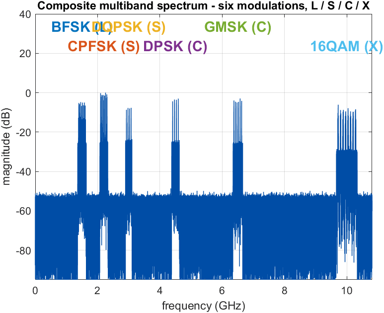
To design and validate such a receiver you first need a realistic stimulus. The transmitter is a MATLAB testbench that synthesizes one composite RF scene deliberately built to mimic a contested multiband battlespace: six independent systems, spanning four bands, each using a different modulation, data rate, and frame structure, each frequency-hopping within its own band — all summed on a common wideband clock, then hit with jamming and thermal noise.
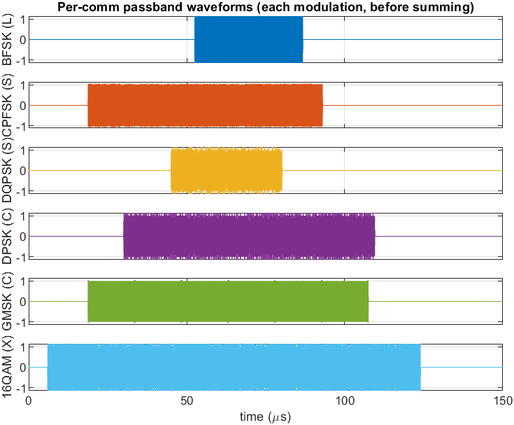
In the time domain, one panel per system (before summing), the systems differ in burst duration, activity, and hop cadence — the high-rate 16-QAM stream is busy across almost the whole record while the low-rate links send short, sparse bursts.
The six systems
| System | Band | Carrier | Data rate | Modulation | Ch. |
|---|---|---|---|---|---|
| BFSK | L | 1.5 GHz | 12 Mb/s | Binary FSK (non-coherent) | 4 |
| CPFSK | S | 2.2 GHz | 8 Mb/s | Continuous-phase FSK | 6 |
| DQPSK | S | 3.0 GHz | 12 Mb/s | Differential QPSK | 4 |
| DPSK | C | 4.5 GHz | 5 Mb/s | Differential PSK | 4 |
| GMSK | C | 6.5 GHz | 8 Mb/s | Gaussian MSK | 6 |
| 16-QAM | X | 10 GHz | 100 Mb/s | 16-QAM (coherent) | 8 |
Frequency hopping
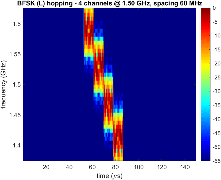
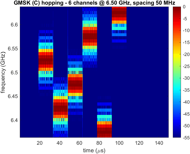
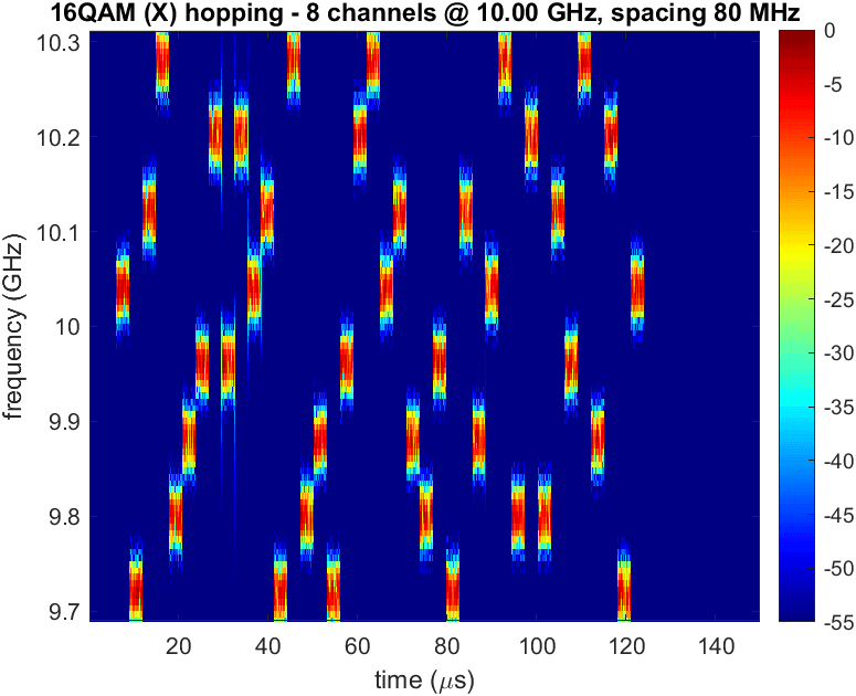
Each system hops among its own set of channels within its band. A per-system spectrogram makes the hop pattern explicit — shown here for three examples spanning the rate range.
Message-structure diversity
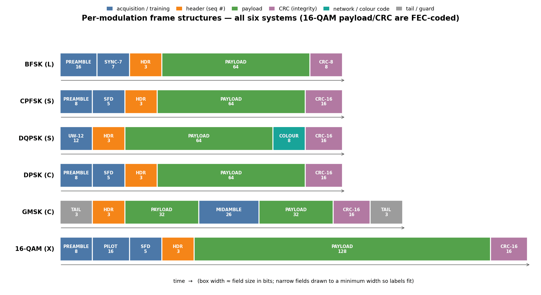
Each modulation family carries its own frame layout, and a receiver must match the per-family structure to acquire and decode it — from front-loaded FSK preambles, to a DQPSK burst led by a unique word and trailed by a colour code, to a GSM-style GMSK burst with a mid-burst training sequence, to a coherent 16-QAM frame with a pilot and forward error correction.
Realistic impairments — nominal vs impaired
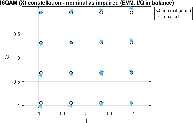
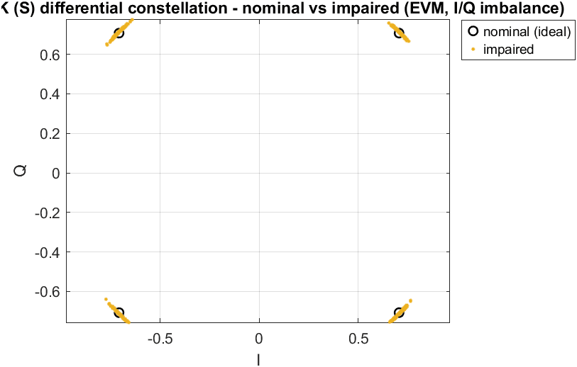
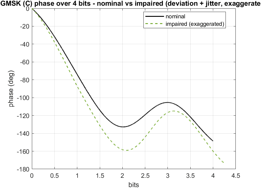
Every burst carries the hardware- and propagation-induced errors a real link fights: carrier frequency offset / Doppler (acute on satellite and fast-target links), oscillator phase noise, I/Q gain and phase imbalance, symbol-clock jitter, and deviation / BT tolerances. Each system is shown against its own ideal (error-free) reference so the effect is visible directly.
Jamming
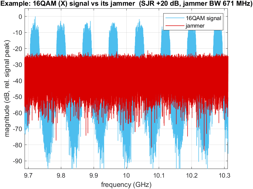
A configurable barrage noise jammer can be placed on each band. Below, the signal-to-jammer ratio is set to 20 dB: the jammer's noise floor rises to roughly 20 dB below the signal peaks and blankets every hop channel of the 16-QAM link, so no single channel can hop clear of it.
Next in the series
Article 2 turns from stimulus to design: frequency, data-rate, and decimation planning; a look at the RF front-end simulation; and the channelization stage — polyphase channelizers and digital down-converters, with filter-bank and decimating-filter design. The transmitter code and documentation are on GitHub.